|
No hay comentarios de productos.
Main Lever
Disassembly Procedure
1. Release 2 Locking Tabs (C) and Locking Tab (D). Then, remove the Main Lever. Locking Tab (D) Locking Tabs (C)
P5 Arm Unit and Main Lever Drive Arm
Disassembly Procedure
1. Pull up on the P5 Arm Unit. 2. Turn the Main Lever Drive Arm fully counterclockwise as shown. 3. Pull up on the Main Lever Drive Arm.
9 Main Lever
11 Main Lever Drive Arm Turn
10 P5 Arm Unit
Groove of Main Lever Guide Fig. J6-1 Fig. J7-1
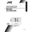
Reassembly Notes
1. Installation/Alignment of Main Lever 1) Make sure that the 2 holes of Loading Rack Unit are aligned with the holes on chassis (Through holes). 2) Turn the P5 Arm Unit to the Capstan Rotor Unit Shaft side. 3) Turn the T Brake Unit to the T Reel Table side. 4) Position the Main Lever so that the Loading Rack Unit Pin fits in the niche of Main Lever. Confirm that pins and bosses are in the position and that the hole of Main Lever is aligned with the hole on chassis (Through hole) as shown. Then, install the Main Lever. 5) Push down the Locking Tabs (C) to set in the groove of Main Lever Guide.
Changing Lever A Boss Loading Rack Unit Pin Capstan Rotor Unit Shaft
Reassembly Notes
1. Alignment of Main Lever Drive Arm 1) Install the Main Lever Drive Arm so that the hole (C) is aligned with the hole on the chassis Through hole (C)) as shown.
Chassis Pin
Main Lever Drive Arm
Loading Rack Unit
Through Holes
Main Lever
Locking Tabs (C)
P5 Arm Unit
P5 Arm Unit Boss Locking Tab (D) Main Lever Drive Arm Pin T Brake Unit Boss
Through Hole (C)
Niche
Main Lever Guide
Fig. J7-2
S Brake Arm Unit Pin Through Hole
T Brake Unit T Reel Table
Fig. J6-2
2-12
|