- SERVICING NOTES
- GENERAL
- Location and Function of Controls
- DISASSEMBLY
- Rear Plate Removal
- Cabinet (Upper) Removal
- Front Panel Removal
- MD Section Removal
- Heat Sink, Diode Board, VOL Board Removal
- Main Board, Power Board Removal
- TEST MODE
- ADJUSTMENTS
- Mechanical Adjustments
- Electrical Adjustments
- EXPLANATION OF IC TERMINALS
- DIAGRAMS
- Block Diagram (Main Section)
- Block Diagram (CD Section)
- Printed Wiring Boards (Main Section)
- Schematic Diagram (Main Section)
- Schematic Diagram (TC Section)
- Printed Wiring Boards (TC Section)
- Printed Wiring Boards (CD Section)
- Schematic Diagram (CD Section)
- Printed Wiring Boards (Display Section)
- Schematic Diagram (Display Section)
- EXPLODED VIEWS
- Chassis Section
- Front Panel Section
- Cabinet (Upper) Section
- Mechanism Deck Section (1)
- Mechanism Deck Section (2)
- Optical Pick - up Section
- Speaker Section
- ELECTRICAL PARTS LIST
No hay comentarios de productos.
PMC-303L
AEP Model UK Model
SERVICE MANUAL
CORRECTION - 1
Correct your Service Manual as shown below.
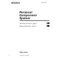
8-6. OPTICAL PICK-UP SECTION (KSM-213BAN/S-N)
r
!: Correct portion
INCORRECT
Part No. Description ���������������� Part No. 2-627-003-01
Page Ref.No.
256
CORRECT
Description GEAR (B) (RP)
253
not supplied
@
254
@
256 @
62
252
#11
M702 S701
255
251
M701
(SPM-97032) 98B0250-1 Printed in Japan © 1998.2 Published by Quality Engineering Dept. (Shibaura)
Sony Corporation
9-923-037-91
Personal A&V Products Company
|