Su carrito de compras está vacío
 
English Polski Spanish 
Buscar un manual
 

(p.Ej. AA-V20EG JVC, ZX-7 Sony)
PayPal 1000+ rating Secure, Encrypted Checkout.
 
Usuarios conectados
Actualmente hay 5690 visitantes online.
Productos
Información
Destacado
Inicio >> SHARP >> PG-M10SU Manual de Servicio
 
 0 artículo(s) en Su carrito 

SHARP PG-M10SU
Manual de Servicio


¡Twitee acerca de este producto y obtenga $1.00 de crédito en la tienda para uso!
  • Contiene diagramas del circuito
  • Descargable
  • Formato PDF
  • Manual completo
  • Idiomas: English, German
Precio: $4.99

Descripción del SHARP PG-M10SU Manual de Servicio

Manual de servicio completo en formato digital (archivo PDF). Los manuales de servicio por lo general contienen diagramas de circuitos, tarjetas de circuitos impresos, consejos para reparación, diagramas de cableado, diagramas de bloque y lista de refacciones. El Manual de Servicio (a veces llamado Manual de Reparación) es usado principalmente por los técnicos.

Si tan solo quiere saber cómo utilizar su televisión, reproductor de vídeo, reproductor de mp3, etc. Quizá lo que necesita es el Manual del Propietario. Después de colocar la orden le enviaremos las instrucciones de descarga a su dirección de e-mail.

The manual is available in languages: English, German

Not yet ready
You must purchase it first

Opiniones de los clientes
No hay comentarios de productos.

TEXT_PDF_SNIPPET
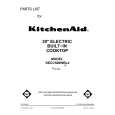
PG-M10SU/SE PG-M10XU/XE 14)Lamp housing (See Fig. 15.) Remove the three screws (S-7) shown in Fig. 15, and detach the lamp housing from the bottom cover. Remove the screws (S-15) shown in Fig. 15, and detach the thermistor and thermistor plate. Remove the screw (S-7) shown in Fig. 15, and detach the ballast lock base. With the lamp housing taken out, the 40 fan assembly (DC) can be detached. Note: Take note of the wiring for the 40 fan assembly, which goes below the lamp housing.
40FAN(DC) S-7 Lamp housing S-15 Thermistor Ass�y S-7 Thermistor Plate S-15
Front Foot

16)Front and rear feet (See Fig. 17.) As shown in Fig. 17, press the hook (1) first and then the hook (2). Remove the front feet. Turn the rear feet away out of place. Remove the screw (S-7) shown in Fig. 17, and detach the lamp limit switch.

S-7 Lamp Limit Switch Rear Foot

Fig. 17

Fig. 15 15)Power unit (See Fig. 16.) Remove the two screws (S-7) shown in Fig. 16, and detach the fan base from the cover. Remove the screws (S-5 and S-10 one each) and the two D/M spacers shown in Fig. 16, and detach the power unit.
S-5 S-10 D/M Spacer

40FAN(L) S-7 Power Unit

S-7 Fan Base

Fig. 16

14

Quizás también quiera comprar

$4.99

SX-K700 TECHNICS
Manual de Usuario

Manual del propietario completo en formato digital. El manual estará disponible para descarga como …

$4.99

CJ-V51 PIONEER
Manual de Servicio

Manual de servicio completo en formato digital (archivo PDF). Los manuales de servicio por lo genera…

$4.99

GRAND PRIX ELECTRONIC 754 BECKER
Manual de Servicio

Manual de servicio completo en formato digital (archivo PDF). Los manuales de servicio por lo genera…

$4.99

SX-PR602 TECHNICS
Manual de Servicio

Manual de servicio completo en formato digital (archivo PDF). Los manuales de servicio por lo genera…

$4.99

EV-S1000E SONY
Manual de Usuario

Manual del propietario completo en formato digital. El manual estará disponible para descarga como …

$4.99

GRAND PRIX ELECTRONIC 780 BECKER
Manual de Servicio

Manual de servicio completo en formato digital (archivo PDF). Los manuales de servicio por lo genera…

$4.99

AG7330 PANASONIC
Manual de Servicio

Manual de servicio completo en formato digital (archivo PDF). Los manuales de servicio por lo genera…

$4.99

EVO-9850 VOLUME 1 SONY
Manual de Servicio

Manual de servicio completo en formato digital (archivo PDF). Los manuales de servicio por lo genera…
>
Parse Time: 0.246 - Number of Queries: 125 - Query Time: 0.08