|
|
|
Productos
|
|
Información
|
|
Destacado
|
|
|
 |
|
|
No hay comentarios de productos.
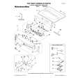
D309 (A1) (red)
: 9-pin data reception (9-pin CPU � main CPU) indicator Turns on while the main CPU is receiving data from the 9-pin CPU. CPU) indicator Turns on while the main CPU is sending data to the 9-pin CPU. : 9-pin data reception (SCU � 9-pin CPU) indicator
D310 (A1) (green) : 9-pin data send (9-pin CPU � main
Switches S301 (C2) : RESET switch CPU (IC304) reset switch S302 (A2) : Mode setting S302-1, 2: Destination setting
S302-1 OFF ON OFF ON S302-2 OFF OFF ON ON Destination setting For UC For J For CE For UC
D316 (A1) (red)
Turns on while the 9-pin CPU is receiving data from the SCU (Serial Control Unit, IC306). D317 (A1) (green) : 9-pin data send (SCU � 9-pin CPU) indicator Turns on while the 9-pin CPU is sending data to the SCU. D601 (A3) (red) : Recorder (playback sound) sound memory write indicator Turns on while writing data into the recorder sound memory. D602 (A3) (yellow) : Recorder (playback sound) sound memory read indicator Turns on while reading data from the recorder sound memory. D603 (A3) (green) : Recorder (playback sound) sound memory IN-point trigger indicator Turns on when cross-fade is applied to the recorder sound memory data at IN-point. D604 (A3) (green) : Recorder (playback sound) sound memory OUT-point trigger indicator Turns on when cross-fade is applied to the recorder sound memory data at OUT-point. : Player (input sound) sound memory write indicator Turns on while writing data into the player sound memory.
S302-3, 4: Device type setting for 9 PIN
S302-3 OFF ON OFF ON S302-4 OFF OFF ON ON Device type setting for 9PIN PCM-7030 (Factory setting) PCM-7050 PCM-7040 PCM-7040
S302-5 to -7 : Reserved S302-8 : Backup memory initialization setting
S302-8: Backup memory initialization setting OFF ON Not initialized when the main power is turned on.(Factory setting) Initialized when the main power is turned on. �-ALL cLEAr-� appears on the display. In the cases as described below, set the destination using S302-1 and -2, then perform initialization. 1. When the SSP-11 board is replaced. 2. When IC309 or IC310 (RAM) on the SSP-11 board is replaced.
D605 (A3) (red)
When any switch of S302-5 to -7 is set to on, the ALARM indicator on the front panel flashes, and �cAution 1-50� is triggered. Factory setting S302-1, -2 ; Items 1 and 2 are set in accordance with destination. S302-3 to -8; off
D606 (A3) (yellow) : Player (input sound) sound memory read indicator Turns on while reading data from the player sound memory. D607 (A3) (green) : Player (input sound) sound memory IN-point trigger indicator Turns on when cross-fade is applied to the player sound memory data at IN-point. D608 (A3) (green) : Player (input sound) sound memory OUT-point trigger indicator 1-6(E)
PCM-7040
|
|
 |
> |
|

