|
No hay comentarios de productos.
KDC-V7521/Y
CIRCUIT DESCRIPTION/ATTENTION
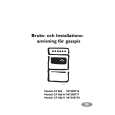
Variable Illumination Circuit
Using a DAC that can be varied in 256 steps between 0V and 5V and varying DAC output voltage, the currents that flow among R7, R9 and R11 are controlled. As a result, the brightness of red, blue and green is adjusted. to the buffer and that will be the input voltage of the V-I converter in the next stage with the voltage waveform of C . The V-I converter has the function of supplying electric current in proportion to the voltage input. For example, let us assume that the current flowing in the red LED is IR, and IR = (Q4 base voltage-VBE) /R7. From this, IR flows in proportion to Q4 base voltage. Therefore, V-I converter will supply current in proportion to the voltage input to red, blue and green LED's, which vary the brightness of LED's. The registor between D1 and V-I converter is the protection registor for limiting power supplied to transistors (Q4-6).
Description of Operation The voltage output from DAC will be in the step-wise waveform as shown in A . When the output voltage is put through R1-3 and C1-3 lowpass filters for removing noise and smoothing voltage waveforms, we get the voltage waveform of B . The voltage that went through the low-pass filters is input
4.7
ILL+B D1 PAN5V DAC
R4 100k
R LOW PASS FILTER 1 2 3 4 R1 R2 R3 100k 100k 100k
R5 100k
G
B
IC1
8 SDA SCL 7 6 VCC SDA AO1 AO2 AO3 NC
Q2
R6 100k
Q1
V
BUFFER
PROTECTION RESISTOR
Q3 Q4
V
(R) (G) (B)
C2 C3 4.7
5 SCA GND
V-I CONVERTER
Q5 Q6
(BOTTOM VIEW)
C1 4.7
A GND
B
R7 270 R8 220
C
A : DAC OUT
B : BUFFER INPUT
C : V-I CONVERTER INPUT
R9 470 R10 150 R11 470 R12 150
V
T
T
T
ATTENTION Assembly pf FPC (Flexible PC board) onto Roller ass�y Turn Roller ass�y by 2 times. Hook the end of Roller ass�y to the tongue. Insert the FPC into the slit of Roller ass�y then release the end of Roller ass�y and the tongue.
FPC tongue
Turn 2 times.
End of Roller ass�y
10
|