KD-G725UT Quantity: 1
$4.99
» View Details
30HFX84 Quantity: 1
$4.99
» View Details
NE-9870C Quantity: 1
$4.99
» View Details
G620 FRYDERYK Quantity: 1
$4.99
» View Details
KG 301 A+ WS Quantity: 1
$4.99
» View Details
S5400DMN Quantity: 1
$4.99
» View Details
002.241.9 Quantity: 1
$4.99
» View Details
H201 Quantity: 1
$4.99
» View Details
FG290-4 Quantity: 1
$4.99
» View Details
WJSX550C Quantity: 1
$4.99
» View Details
32Z33B2 Quantity: 1
$4.99
» View Details
RI1861/00 Quantity: 1
$4.99
» View Details
ADC5305 Quantity: 1
$4.99
» View Details
DTA3220ZL Quantity: 1
$4.99
» View Details
BD921B Quantity: 1
$4.99
» View Details
CDA7842R Quantity: 1
$4.99
» View Details
SADK2GCS Quantity: 1
$4.99
» View Details
CLC700 Quantity: 1
$4.99
» View Details
PHASER740L Quantity: 1
$4.99
» View Details
ART 882/ST-LH Quantity: 1
$4.99
» View Details
CT3328/BT0SA0SG Quantity: 1
$4.99
» View Details
LW15E33C Quantity: 1
$4.99
» View Details
DGF/B 451-0 Quantity: 1
$4.99
» View Details
MMS430/05 Quantity: 1
$4.99
» View Details
DVD622MKI/37 Quantity: 1
$4.99
» View Details
42WP16E Quantity: 1
$4.99
» View Details
F649 Quantity: 1
$4.99
» View Details
AX1101/19 Quantity: 1
$4.99
» View Details
A76/00B Quantity: 1
$4.99
» View Details
LP3000 Quantity: 1
$4.99
» View Details
KESH307BAL5 Quantity: 1
$4.99
» View Details
STJX210L Quantity: 1
$4.99
» View Details
ART 845/G Quantity: 1
$4.99
» View Details
Subtotal: $164.67
 
English Polski Spanish 
Buscar un manual
 

(p.Ej. AA-V20EG JVC, ZX-7 Sony)
PayPal 1000+ rating Secure, Encrypted Checkout.
 
Productos
Información
Destacado
Inicio >> JVC >> HD61Z575 Manual de Servicio
 
 33 artículo(s) en Su carrito 

JVC HD61Z575
Manual de Servicio


¡Twitee acerca de este producto y obtenga $1.00 de crédito en la tienda para uso!
  • Contiene diagramas del circuito
  • Descargable
  • Formato PDF
  • Manual completo
  • Idiomas: English
Precio: $4.99

Descripción del JVC HD61Z575 Manual de Servicio

Manual de servicio completo en formato digital (archivo PDF). Los manuales de servicio por lo general contienen diagramas de circuitos, tarjetas de circuitos impresos, consejos para reparación, diagramas de cableado, diagramas de bloque y lista de refacciones. El Manual de Servicio (a veces llamado Manual de Reparación) es usado principalmente por los técnicos.

Si tan solo quiere saber cómo utilizar su televisión, reproductor de vídeo, reproductor de mp3, etc. Quizá lo que necesita es el Manual del Propietario. Después de colocar la orden le enviaremos las instrucciones de descarga a su dirección de e-mail.

The manual is available in languages:

Not yet ready
You must purchase it first

Opiniones de los clientes
No hay comentarios de productos.

TEXT_PDF_SNIPPET
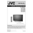
<INNER PWB SIDE> 3.1.18 AV TERMINAL BOARD � Take out the BODY COVER. (1) Remove 5 screws [ A ]. (2) Remove 1 screw [ B ]. (3) Pull out the POWER CORD CLAMP. (4) Remove the nut [ C ] attaching the ANTENNA TERMINAL. (5) Take out the AV TERMINAL BOARD. 3.1.19 SUB DRIVE PWB � Take out the BODY COVER. � Take out the BODY BRACKET. � Take out the MAIN UNIT. (1) Remove 4 screws [ D ]. (2) Take out the PWB HOLDER. (3) Disconnect the connector [CN401] and [CN402]. (4) Remove 6 screws [ E ]. (5) Take out the SUB DRIVE PWB. 3.1.20 POWER PWB � Take out the BODY COVER. � Take out the BODY BRACKET. � Take out the MAIN UNIT. (1) Remove 1 screw [ F ]. (2) Take out the POWER PWB BRACKET. (3) Disconnect the connector [CN90BL], [CN90SE], [CN90AA], [CN90B], [CN90DD] and [CN90G]. (4) Remove 5 screws [ G ]. (5) Take out the POWER PWB. 3.1.21 DIGITAL SIGNAL PWB � Take out the BODY COVER. � Take out the BODY BRACKET. � Take out the MAIN UNIT. � Take out the AV TERMINAL BOARD. � Take out the PWB HOLDER (1) Disconnect the connector [CN001], [CN002], [CN003], [CN0FC] and [CN0LV2]. (2) Remove 1 screw [ H ] attaching the earth wire. (3) Remove 1 screw [ I ]. (4) Remove the both side SHIELD COVER. (5) Take out the DIGITAL SIGNAL PWB. CAUTION: Make sure to perform the "SYSTEM SETTING" on page 1-10, when DIGITAL SIGNAL PWB is replaced.

3.1.22 RECEIVER PWB � Take out the BODY COVER. � Take out the BODY BRACKET. � Take out the MAIN UNIT. � Take out the AV TERMINAL BOARD. � Take out the PWB HOLDER (1) Remove 1 screw [ J ]. (2) Take out the ANALOG PWB BRACKET with PWB. (RECEIVER PWB / ANALOG SIGNAL PWB / REGULATOR PWB) (3) Disconnect the connector [CN10FC], [CN10PH], [CN100R], [CN10PH], [CN100A], [CN100T], [CN100F], [CN10FJ], [CN10FL], [CN10SW], [CN10AA] and [CN10SP]. (4) Remove 4 screws [ K ]. (5) Take out the RECEIVER PWB. 3.1.23 ANALOG SIGNAL PWB � Take out the BODY COVER. � Take out the BODY BRACKET. � Take out the MAIN UNIT. � Take out the AV TERMINAL BOARD. � Take out the PWB HOLDER � Take out the RECEIVER PWB. (1) Disconnect the connector [CN001], [CN002], [CN00D], [CN0J1], [CN0J2], [CN00T], [CN00F] and [CN00G]. (2) Remove 2 screws [ L ]. (3) Take out the ANALOG SIGNAL PWB. 3.1.24 REGULATOR PWB � Take out the BODY COVER. � Take out the BODY BRACKET. � Take out the MAIN UNIT. � Take out the AV TERMINAL BOARD. � Take out the PWB HOLDER � Take out the RECEIVER PWB. (1) Disconnect the connector [CN20D], [CN203] and [CN20B]. (2) Remove 4 screws [ M ]. (3) Take out the REGULATOR PWB. 3.1.25 REAR JACK PWB � Take out the BODY COVER. � Take out the BODY BRACKET. � Take out the MAIN UNIT. � Take out the AV TERMINAL BOARD. (1) Disconnect the connector [CNPH], [CNJ0J2]. (2) Remove 2 screws [ N ]. (3) Take out the REAR JACK PWB.

[CNJ0J1]

and

(No.YA092B)1-15

Quizás también quiera comprar

$4.99

HD-61Z575 JVC
Manual de Usuario

Manual del propietario completo en formato digital. El manual estará disponible para descarga como …
>
Parse Time: 0.446 - Number of Queries: 226 - Query Time: 0.172