GE-35 Quantity: 1
$4.99
» View Details
MW1200XP1 Quantity: 1
$4.99
» View Details
CBV2520 Quantity: 1
$4.99
» View Details
PEGSJ33ISYNCUG Quantity: 1
$4.99
» View Details
FX-350TL Quantity: 1
$4.99
» View Details
SE-MXG9BK Quantity: 1
$4.99
» View Details
ET20RMXTF00 Quantity: 1
$4.99
» View Details
CUMA185KE/ Quantity: 1
$4.99
» View Details
GM-X574 Quantity: 1
$4.99
» View Details
RS675PXYH2 Quantity: 1
$4.99
» View Details
LBTV502CD/CDM Quantity: 1
$4.99
» View Details
WP 68 IX Quantity: 1
$4.99
» View Details
55PL9774/37B Quantity: 1
$4.99
» View Details
900KSVC25 Quantity: 1
$4.99
» View Details
DEH-P4750MP/XN/GS Quantity: 1
$4.99
» View Details
NV-HS825B Quantity: 1
$4.99
» View Details
DMP1000P Quantity: 1
$4.99
» View Details
AVX-P8DVD/UC Quantity: 1
$4.99
» View Details
WVLA4R5C3B Quantity: 1
$4.99
» View Details
ARKANSAS 4635 Quantity: 1
$4.99
» View Details
IRE32301 Quantity: 1
$4.99
» View Details
DWF 401 NB Quantity: 1
$4.99
» View Details
V-410W Quantity: 1
$4.99
» View Details
AWO 415 Quantity: 1
$4.99
» View Details
HS545/33 Quantity: 1
$4.99
» View Details
HS810CD Quantity: 1
$4.99
» View Details
Subtotal: $129.74
 
English Polski Spanish 
Buscar un manual
 

(p.Ej. AA-V20EG JVC, ZX-7 Sony)
PayPal 1000+ rating Secure, Encrypted Checkout.
 
Productos
Información
Destacado
Inicio >> JVC >> GRDVP9EK Manual de Servicio
 
 26 artículo(s) en Su carrito 

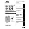
JVC GRDVP9EK
Manual de Servicio


¡Twitee acerca de este producto y obtenga $1.00 de crédito en la tienda para uso!
  • Contiene diagramas del circuito
  • Descargable
  • Formato PDF
  • Manual completo
  • Idiomas: English
Precio: $4.99

Descripción del JVC GRDVP9EK Manual de Servicio

Manual de servicio completo en formato digital (archivo PDF). Los manuales de servicio por lo general contienen diagramas de circuitos, tarjetas de circuitos impresos, consejos para reparación, diagramas de cableado, diagramas de bloque y lista de refacciones. El Manual de Servicio (a veces llamado Manual de Reparación) es usado principalmente por los técnicos.

Si tan solo quiere saber cómo utilizar su televisión, reproductor de vídeo, reproductor de mp3, etc. Quizá lo que necesita es el Manual del Propietario. Después de colocar la orden le enviaremos las instrucciones de descarga a su dirección de e-mail.

The manual is available in languages:

Not yet ready
You must purchase it first

Opiniones de los clientes
No hay comentarios de productos.

TEXT_PDF_SNIPPET
1.6 DISASSEMBLY/ASSEMBLY OF @ OP BLOCK ASSY (CCD BOARD ASSY) 1.6.1 Precautions 1. Carefully handle the CCD IMAGE SENSOR, OP LPF, LENS, etc. during the disassembly work. Pay the most careful attention to the surface of those parts not to get it soiled, scratched or dusty. If some of those surfaces gets soiled with fingerprints, etc., wipe it out with silicone paper, clean chamois, cleaning cloth or the like. 2. The new CCD IMAGE SENSOR is occasionally shipped from the factory as a protection seal is applied onto its transparent glass. If so, leave the protection seal as it is and remove it just before installing the CCD IMAGE SENSOR in the OP BLOCK ASSY. 3. The orientation of the OP LPF is an important factor for installation. If there some marking on the OP LPF, be sure to note it down before removing and to reassemble it very carefully as it was referring to the marking. 1.6.2 Disassembly method 1. Unsolder at the 14 points (SD@) and remove the CCD BOARD ASSY. 2. Remove the two screws (1, 2) and then remove the CCD BASE ASSY. NOTE@a: Carefully remove the CCD BASE ASSY, because the SPACE RUBBER and OP LPF may be removed together with the CCD IMAGE SENSOR.

NOTE@b:When replacing the CCD IMAGE SENSOR, don�t replace it individually but replace the CCD BASE ASSY in whole with a new one. 1.6.3 Assembly method 1. Install the OP LPF with the @ OP BLOCK ASSY. 2. With the SPACER RUBBER left attached to the CCD BASE ASSY, install the assembly in the OP BLOCK ASSY and clamp it using the two screws (1, 2). 3. Set the CCD BOARD ASSY in the CCD BASE ASSY, and fasten it by soldering at the 14 points (SD@). 1.6.4 Replacement of service parts Service parts to be supplied for the OP BLOCK ASSY are as follows. When replacing a part, be very careful not to get the FPC wire broken or damaged by soldering (overheating). 1. FOCUS MOTOR 2. ZOOM MOTOR 3. IRIS MOTOR UNIT NOTE@c: When soldering the FPC wire of the FOCUS MOTOR or ZOOM MOTOR during the replacement work, be sure to keep the tip of a soldering iron approximately 1 mm above the terminal.

IRIS MOTOR UNIT includes one FPC ASSY NOTE@d:The and two sensors.

�3

�5 �4
(S 12 b)
CCD SIDE OP SIDE BLUE

(S 12 b) (S 12 c)

CCD BOARD ASSY <05> (SD 12 ) (S 12 a)

�8
NOTE 12 d IRIS MOTOR UNIT (S 12 c)

�9
(S 12 c)

�1

�2
(S 12 a) CCD BASE ASSY NOTE 12 a,b SPACER RUBBER OP LPF NOTE 12 a

FOCUS MOTOR NOTE 12 c

�7 �6
(S 12 c) (S 12 c)

OP BLOCK

ZOOM MOTOR NOTE 12 c

� : 0.118 N�m (1.2 kgf�cm)
Fig. 1-6-1 1-10

Quizás también quiera comprar

$4.99

GR-DVP9EK JVC
Manual de Usuario

Manual del propietario completo en formato digital. El manual estará disponible para descarga como …
>
Parse Time: 1.067 - Number of Queries: 190 - Query Time: 0.649