Su carrito de compras está vacío
 
English Polski Spanish 
Buscar un manual
 

(p.Ej. AA-V20EG JVC, ZX-7 Sony)
PayPal 1000+ rating Secure, Encrypted Checkout.
 
Usuarios conectados
Actualmente hay 5809 visitantes online.
Productos
Información
Destacado
Inicio >> SHARP >> ER-A770 Manual de Servicio
 
 0 artículo(s) en Su carrito 

SHARP ER-A770
Manual de Servicio


¡Twitee acerca de este producto y obtenga $1.00 de crédito en la tienda para uso!
  • Contiene diagramas del circuito
  • Descargable
  • Formato PDF
  • Manual completo
  • Idiomas: English, German
Precio: $4.99

Descripción del SHARP ER-A770 Manual de Servicio

Manual de servicio completo en formato digital (archivo PDF). Los manuales de servicio por lo general contienen diagramas de circuitos, tarjetas de circuitos impresos, consejos para reparación, diagramas de cableado, diagramas de bloque y lista de refacciones. El Manual de Servicio (a veces llamado Manual de Reparación) es usado principalmente por los técnicos.

Si tan solo quiere saber cómo utilizar su televisión, reproductor de vídeo, reproductor de mp3, etc. Quizá lo que necesita es el Manual del Propietario. Después de colocar la orden le enviaremos las instrucciones de descarga a su dirección de e-mail.

The manual is available in languages: English, German

Not yet ready
You must purchase it first

Opiniones de los clientes
No hay comentarios de productos.

TEXT_PDF_SNIPPET
8. Removing and replacing the LCD unit
1) Remove the four fixing screws cabinet . of the display unit from the top

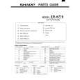
9. Expansion RAM Board : UP-P02MB2
Make sure to save data before installing this option 1) Remove the top cabinet. 2) Install the Expansion RAM Board on the Main PWB. to the Option RAM connector

2

a) Insert the Expansion RAM Board aslant into the option RAM connector. b) Push the RAM disk unit Expansion RAM Board is locked by the arms of option RAM connector. It is possible to install one UP-P02MB2. Be careful of the direction of Expansion RAM Board to be installed. Install the Expansion RAM Board with the notch part of the PWB (Figure A) come right. Installing the Expansion RAM Board in the wrong direction may damage the connector part or make the machine out of order.

3

A 1

3

1

Fig. 5 2) Remove the two fixing screws unit. of the LCD unit in the display

3) The LCD unit is assembled with seven pawls. Remove the pawls in the order of to as shown in the figure.

LCD cabinet hear side

c

d

e

b

f

Fig. 7 3) Removing the Expansion RAM Board. a) Open the arms of option RAM connector right and left. b) The Expansion RAM Board will be lifted automatically.

a

g

10. RS232 I/F: ER-A7RS & EFT I/F: ER-02EF
4
1) Remove the rear cover. 2) Remove the two screws Fig. 6 3) Insert the I/F PWB from the shassis.

to the connector. .

4) Fix the I/F bracket to the shassis with screws 5) Install the ferrite core 6) Install the Nylon band . to the cables.

Quizás también quiera comprar

$4.99

ER-A770 SHARP
Manual de Usuario

Manual del propietario completo en formato digital. El manual estará disponible para descarga como …

$4.99

ER-A770 SHARP
Catálogo de piezas

Únicamente Catálogo de Partes. Está disponible en formato PDF. Muy útil si su equipo se ha averi…
>
Parse Time: 0.313 - Number of Queries: 105 - Query Time: 0.106