|
No hay comentarios de productos.
DV-F727, DV-F07
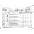
2 Disc-select Rotation Adjustment
DC power supply
Connection Diagram for Adjustment
V
A
�8V GND +8V
VOLB ASSY
VR601 KN601 Player
JIG (Peak hold circuit)
Digital multimeter
SW INPUT OUTPUT
GND (Under Base)
Adjustment Procedure
1. 2. 3. 4. 5. 6. 7. 8. 9. 10. 11. 12. 13. 14. Connect all equipment as shown in the diagram. Turn on the power (Normal mode) and put the test disc in the No. 1 disc slot. Enter the Test mode by pressing the "ESC" � "TEST" button of the test mode remote control unit. Press the "DIG/ANA" button of the test mode remote control unit. (Disc 1 is clamped.) Adjust VR601 on the VOLB Assy so that the voltage becomes 830 ± 5mV. Switch the connection of Digital multimeter from INPUT to OUTPUT of the Jig. Press the "DIG/ANA" button of the test mode remote control unit. (Starts the disc detection and peak hold .) Confirm the voltage during the disc detection. If voltage is between 920 to 1170mV, go to step 13. If not, go to step 9. Switch the connection of Digital multimeter form OUTPUT to INPUT of the Jig. Press the "DIG/ANA" button of the test mode remote control unit. (Disc 1 is clamped.) Adjust VR601 to become the value for addition (or subtraction) that to have an adjustment voltage. (Refer to the following table.) Perform steps 6 to 8 again and confirm the voltage during the disc detection. If voltage is between 920 to 1170mV, go to step 13. If not, repeat steps 9 to 12. Confirm that Disc No. display doesn't become "1" others when you turn the Jog dial. Release the Test mode by pressing the "ESC" button or turn off the power. Adjustment voltage value Peak hold voltage (mV) to 859 859 to 879 879 to 920 920 to 1170 1170 to 1309 1309 to 1520 1520 to 1840 1840 to 2220 2220 to Adjustment voltage (mV) +20 +10 +5 OK -5 -10 -20 -30 -40
64
|