|
No hay comentarios de productos.
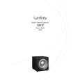
CSW-10
Service Bulletin
Service Bulletin INF2004-02 � September 2004 To: All Infinity Service Centers This is considered a Minor repair
Model: Beta CSW-10 Subject: Premature Limiting A small number of CSW-10 subwoofers may limit the amplifer output prematurely when they are driven to high volume levels. This may result in the subwoofer �popping�, and then a lower than normal output. A normal output will not return until the volume is decreased, or the subwoofer is switched Off, then On again. In the event you receive a CSW-10 subwoofer with a complaint of �Premature Limiting When Driven At High Levels�, follow the procedure below to correct this condition: Synopsis: Add two diodes to the limiter section on the MAIN PCB, D90 and D91. 1) Remove the amplifier assembly from the cabinet by removing the (12) screws located around the perimeter of the plate (Red circles in image); it will still be connected by the speaker wires. 2) Remove the (2) screws used to secure the plastic cover to the amp panel (Blue arrows in image), separate the panel from the plastic cover, and unplug the speaker wires from MAIN PCB (Red & Blk). 3) Remove the MAIN PCB from the faceplate: a. Remove the (5) screws used to secure the amp module to the front panel (Pointing fingers in image). b. Unplug P1 Signal Harness (Harness with white wires) c. Remove ground wire (Black wire with ring terminal) d. Unplug Power Transformer wires (Red-White-Red) 4) Locate D90 & D91 trace locations close to the main power capacitors (refer to the image) 5) Solder two RLS4148 SMD Diodes in their designated areas, D90 and D91, Infinity part # 054-414803-100. IMPORTANT: POLARITY - Diodes should be soldered with their cathode facing into the amplifier assembly, anodes facing the PCB edge of the amplifier. You should be able to solder the diodes in place without PCB disassembly from the heatsink plate with care, and a long, pointed soldering tip. 6) Re-Attach the MAIN PCB to the faceplate, following in reverse order items #3a-d. Assure that the power transformer wires are connected with White in the center and Red wires to the outer sides of the rectifier. Location of D90 & D91
(Installed)
9
|