|
|
|
Productos
|
|
Información
|
|
Destacado
|
|
|
 |
|
|
No hay comentarios de productos.
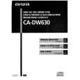
ELECTRICAL ADJUSTEMENT-1/1 PRACTICAL SERVICE FIGURE
L003 BAR ANT 3 1. AM IF Adjustment L007 .................................................................................... 530 kHz 2. AM VT Adjustment Settings: � Test point: C39 + (TP1) � Adjustment location: L004 Method: Set to AM 1710 kHz adjust L004 so that the test point becomes 5.6 V ± 50 mV L005 3. AM Tracking Adjustment L003 .................................................................................... 600 kHz TC001 ............................................................................... 1400 kHz 4. FM VT Adjustment TC001 24 2 3 Settings: � Test point: C39 + (TP1) � Adjustment location: L006 Method: Set to FM 108 MHz adjust L006 so that the test point becomes 5.6 V ± 50 mV 5. FM Tracking Adjustment L005 ..................................................................................... 98 MHz Distortion: (Input 88 dB) Intermediate frequency:
< TUNER SECTION > < FM SECTION >
Sensitivity: (THD 3%) Signal to Noise Ratio: (Input 32 dB) Distortion: (Input 32 dB) Intermediate frequency: Stereo separation: Less than 22 dB (87.5 MHz) Less than 22 dB (98.0 MHz) Less than 22 dB (108.0MHz) More than 55 dB (at 98.0 MHz) Less than 3.0% (at 98.0 MHz) 10.7 MHz ±0.3 MHz More than 18 dB (at 1 kHz)
FRONT C.B
MAIN C.B
L007 1 IC001
5 9
SFR430
C39 4
L006 L004
< AM SECTION >
Sensitivity: (S/N 10 dB) Less than 52 dB (at 600 kHz) Less than 50 dB (at 1000 kHz) Less than 50 dB (at 1400 kHz) Less than 3% 530 kHz ± 5 kHz
< CASSETTE SECTION > < TAPE SECTION >
6. Bias frequency Adjustment L330 ......................................................................... 56 kHz ± 2 kHz 7. Tape speed Adjustment Settings: � Test tape: MT111 � Test point: PHONES JACK (J251) � Adjustment location: SFR761 L330 6 Method: Play back the test tape and adjust so that the output frequency is 3000 Hz ±30 Hz. Tape speed: Wow & flutter: Take-up torque: FF torque: Rew torque: Back tension: S/N ratio: Distortion: Noise (PB): 3000 Hz ± 60 Hz Less than 0.35% (JIS RMS) 30-60 g-cm (DECK 1/2) 55-140 g-cm (DECK 1/2) 55-140 g-cm (DECK 1/2) 1-5 g-cm More than 50 dB (DC) Less than 3.0% (PB) Less than 0.9 mV (DC) Less than 15 mV (AC VOL max)
J251 SFR761 78 7
8. Azimuth Adjustment Settings: � Test tape: TTA-320 � Test point: PHONES JACK (J251) � Adjustment location: Azimuth adjustment screw Method: Play back the 8kHz signal of the test tape and adjust screw so that the output becomes maximum.
< CD SECTION >
9. Focus Bias Adjustment Settings: � Test CD: TCD-782 (A-BEX) � Test point: IC401 PIN20, PIN58 � Adjustment location: SFR430 Method: Play back the #15 of the test CD and adjust SFR430 so that the voltage between pin20 and pin 58 of IC401 becomes 0V ± 0.1 mV.
RPH/PH
8
-24-
|
|
|
> |
|