| » View Shopping Cart | |
 | Quantity: 1 $4.99 » View Details |
 | Quantity: 1 $4.99 » View Details |
 | Quantity: 1 $4.99 » View Details |
 | Quantity: 1 $4.99 » View Details |
 | Quantity: 1 $4.99 » View Details |
 | Quantity: 1 $4.99 » View Details |
 | Quantity: 1 $4.99 » View Details |
 | Quantity: 1 $4.99 » View Details |
 | Quantity: 1 $4.99 » View Details |
 | Quantity: 1 $4.99 » View Details |
 | Quantity: 1 $4.99 » View Details |
 | Quantity: 1 $4.99 » View Details |
 | Quantity: 1 $4.99 » View Details |
 | Quantity: 1 $4.99 » View Details |
 | Quantity: 1 $4.99 » View Details |
 | Quantity: 1 $4.99 » View Details |
 | Quantity: 1 $4.99 » View Details |
 | Quantity: 1 $4.99 » View Details |
 | Quantity: 1 $4.99 » View Details |
 | Quantity: 1 $4.99 » View Details |
 | Quantity: 1 $4.99 » View Details |
 | Quantity: 1 $4.99 » View Details |
 | Quantity: 1 $4.99 » View Details |
 | Quantity: 1 $4.99 » View Details |
 | Quantity: 1 $4.99 » View Details |
 | Quantity: 1 $4.99 » View Details |
 | Quantity: 1 $4.99 » View Details |
 | Quantity: 1 $4.99 » View Details |
 | Quantity: 1 $4.99 » View Details |
 | Quantity: 1 $4.99 » View Details |
 | Quantity: 1 $4.99 » View Details |
 | Quantity: 1 $4.99 » View Details |
 | Quantity: 1 $4.99 » View Details |
 | Quantity: 1 $4.99 » View Details |
 | Quantity: 1 $4.99 » View Details |
 | Quantity: 1 $4.99 » View Details |
 | Quantity: 1 $4.99 » View Details |
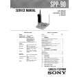 | Quantity: 1 $4.99 » View Details |
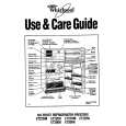 | Quantity: 1 $4.99 » View Details |
 | Quantity: 1 $4.99 » View Details |
 | Quantity: 1 $4.99 » View Details |
 | Quantity: 1 $4.99 » View Details |
 | Quantity: 1 $4.99 » View Details |
 | Quantity: 1 $4.99 » View Details |
 | Quantity: 1 $4.99 » View Details |
 | Quantity: 1 $4.99 » View Details |
 | Quantity: 1 $4.99 » View Details |
 | Quantity: 1 $4.99 » View Details |
 | Quantity: 1 $4.99 » View Details |
 | Quantity: 1 $4.99 » View Details |
 | Quantity: 1 $4.99 » View Details |
 | Quantity: 1 $4.99 » View Details |
 | Quantity: 1 $4.99 » View Details |
 | Quantity: 1 $4.99 » View Details |
 | Quantity: 1 $4.99 » View Details |
 | Quantity: 1 $4.99 » View Details |
 | Quantity: 1 $4.99 » View Details |
 | Quantity: 1 $4.99 » View Details |
 | Quantity: 1 $4.99 » View Details |
 | Quantity: 1 $4.99 » View Details |
 | Quantity: 1 $4.99 » View Details |
 | Quantity: 1 $4.99 » View Details |
 | Quantity: 1 $4.99 » View Details |
 | Quantity: 1 $4.99 » View Details |
 | Quantity: 1 $4.99 » View Details |
 | Quantity: 1 $4.99 » View Details |
 | Quantity: 1 $4.99 » View Details |
 | Quantity: 1 $4.99 » View Details |
 | Quantity: 1 $4.99 » View Details |
 | Quantity: 1 $4.99 » View Details |
 | Quantity: 1 $4.99 » View Details |
 | Quantity: 1 $4.99 » View Details |
 | Quantity: 1 $4.99 » View Details |
 | Quantity: 1 $4.99 » View Details |
 | Quantity: 1 $4.99 » View Details |
 | Quantity: 1 $4.99 » View Details |
 | Quantity: 1 $4.99 » View Details |
 | Quantity: 1 $4.99 » View Details |
 | Quantity: 1 $4.99 » View Details |
 | Quantity: 1 $4.99 » View Details |
 | Quantity: 1 $4.99 » View Details |
 | Quantity: 1 $4.99 » View Details |
 | Quantity: 1 $4.99 » View Details |
 | Quantity: 1 $4.99 » View Details |
 | Quantity: 1 $4.99 » View Details |
 | Quantity: 1 $4.99 » View Details |
 | Quantity: 1 $4.99 » View Details |
 | Quantity: 1 $4.99 » View Details |
 | Quantity: 1 $4.99 » View Details |
 | Quantity: 1 $4.99 » View Details |
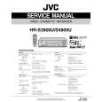 | Quantity: 1 $4.99 » View Details |
 | Quantity: 1 $4.99 » View Details |
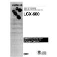 | Quantity: 1 $4.99 » View Details |
 | Quantity: 1 $4.99 » View Details |
 | Quantity: 1 $4.99 » View Details |
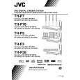 | Quantity: 1 $4.99 » View Details |
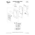 | Quantity: 1 $4.99 » View Details |
 | Quantity: 1 $4.99 » View Details |
 | Quantity: 1 $4.99 » View Details |
 | Quantity: 1 $4.99 » View Details |
 | Quantity: 1 $4.99 » View Details |
 | Quantity: 1 $4.99 » View Details |
 | Quantity: 1 $4.99 » View Details |
 | Quantity: 1 $4.99 » View Details |
 | Quantity: 1 $4.99 » View Details |
 | Quantity: 1 $4.99 » View Details |
 | Quantity: 1 $4.99 » View Details |
 | Quantity: 1 $4.99 » View Details |
 | Quantity: 1 $4.99 » View Details |
 | Quantity: 1 $4.99 » View Details |
 | Quantity: 1 $4.99 » View Details |
 | Quantity: 1 $4.99 » View Details |
 | Quantity: 1 $4.99 » View Details |
 | Quantity: 1 $4.99 » View Details |
 | Quantity: 1 $4.99 » View Details |
 | Quantity: 1 $4.99 » View Details |
 | Quantity: 1 $4.99 » View Details |
 | Quantity: 1 $4.99 » View Details |
 | Quantity: 1 $4.99 » View Details |
 | Quantity: 1 $4.99 » View Details |
 | Quantity: 1 $4.99 » View Details |
 | Quantity: 1 $4.99 » View Details |
 | Quantity: 1 $4.99 » View Details |
 | Quantity: 1 $4.99 » View Details |
 | Quantity: 1 $4.99 » View Details |
 | Quantity: 1 $4.99 » View Details |
 | Quantity: 1 $4.99 » View Details |
 | Quantity: 1 $4.99 » View Details |
 | Quantity: 1 $4.99 » View Details |
 | Quantity: 1 $4.99 » View Details |
 | Quantity: 1 $4.99 » View Details |
 | Quantity: 1 $4.99 » View Details |
 | Quantity: 1 $4.99 » View Details |
 | Quantity: 1 $4.99 » View Details |
| Subtotal: $668.66 | |


