|
|
|
Productos
|
|
Información
|
|
Destacado
|
|
|
 |
|
|
No hay comentarios de productos.
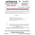
DUAL BAND 8900 AUDIO LOGIC BLOCK DIAGRAM
to U501, 42 RX_ACQ DM_CS TX_KEY SPI_MI to U501 SPI_MO SPI_SCK MDM_RD MDM_WR SPI_RFCS RF_START RESET RX_EN 14 15 16 2 57 122 18, 40, 48 56, 69, 112, 126 17 19 1, 9, 36, 46 51 120 DUAL_CS 119 104 102 101 DP_EN RAM2CS RAM1CS to U704, 39 ROM1CS to U702, 26 to U702, 16 to J2, 8 to J2, 2 to U704, 40 20 37 17 48 35 217 Hz WAVEFORM NEEDED HERE ! 13_DCLK_B from U201, 59 + 2,75V 123 5 6 10 11 12
LOGIC BOARD SIGNALS
Measured in standby mode
U704
RX_EN
2.8mVpp 10ms / cm From the CPU (U701). When high, Rx path enabled and low muted. 1. Enables the Rf switch (U400) for receive mode. 2. Biases the mixer Q420, and low noise amp (Q418). From CPU (U701), but inverted by Q501. High when 1. Enable the Rf switch for transmit mode & also the GIFSYN for transmit mode. 2. Supply Voltage for the PAC IC. 3. Isolates RF, by switching the PA Bias Circuitry ( Not shown). Controlled at power up by GCAP (U900) & CPU (U701). 1. Connected to CPU (U701), BIC (U703), Modem (U501) & Speech coder (U801). After power up sequence, any chip can hold RESET low to power phone off if there is a problem. From CPU (U701) to Eprom. 1. Chip Enable controlling read/write access to and from Eprom (U702).
RESET U705 EEPROM
SRAM
TX_EN
7Vpp 10ms / cm
RESET
power on
2,8Vrms 200ms / cm
U701 Call PROCESSOR
100
DATA BUS
U703 BIC
U702 FLASH
DUAL_CS
2.8Vpp 100ns / cm
DATA BUS ADDRESSS BUS
BIC_INT TXD - to J400, 14 RXD - to J400, 14 + 2,75V 32 31 34 33 38 40 39
ADDRESSS BUS
64 BATT_SENSE DAC_OUT U701, 17, 19
RAM1_CS
2.8Vpp 100ns / cm
From CPU (U701) to SRAM. 1. Chip Enable controlling read/write access to and from 1st half of SRAM (U704).
From CPU (U701) to SRAM.
A/D
46
D/A
58 1
RAM2_CS
2.8Vpp 100ns / cm
1. Chip Enable controlling read/write access to and from 2nd half of SRAM (U704).
133 4 67
DATA BUS
ROM1_CS
2.8Vpp 100ns / cm
From CPU (U701) to Eprom. 1. Chip Enable controlling read/write access to and from Eprom (U702).
ADDRESSS BUS
+4.75V
65
66
50, 52, 54 73, 108, 125
12
(non-voiced data)
14 J400
DP_EN
start up or press key
2.8Vpp 100ns / cm
From CPU (U701) to display, via connector J101. 1. Processor selects to enable display. When high, the display is enabled and low disabled.
C
E
Q504
B C C
MF_INT BIC_INT B C
SC_INT CR605 MF_INT
start up or press key 2ns / cm 2.8Vpp
Speech Coder Interface. This is a signal from uP (U701) to Speech Coder (U801). 1) This is a 20ms timing signal from U701 which times the decoding and encoding function of the Speech Coder U801. From BIC to uP. This signal periodically interrupts the uP at 217Hz. During Power Saving mode this signal is set to DC. From BIC to uP. This signal interrupts the uP for a number of reasons. 1. Keypad detection 2. Power Sense 3. SIM Functions 4. DSC Bus Status Indicators From butt plug (J600) to BIC chip (J600).. This is a comms link from an external peripherale and the phone, andignition status of the information or speech information. It is also used to sense the presence of a DHFA and the could be either data DHFA with DC levels
PAC_ENABLE
Q503
E
+2.75V
E
Q501
B
+ 2,75V
J400
2
4
5
10 13 11
BIC_INT
press a key
2.8Vpp 1ms / cm
TX_ENABLE 7, 19, 26, 50, 56 66, 75, 85, 100
4 2 Q602 R602
5-8 Q601 4 1-3
15
2.8Vpp 50us / cm
2.8Vpp
Encoded Voice Data
UPLINK
CHARGER
17 47 MIC 1 2
UPLINK
10us / cm
U801
DOWNLINK
U803 CODEC
13 8 D/A A/D
18 19 1 4
16 10
ISENSE
-
9
SPEECH CODER
DOWNLINK
5Vpp 10us / cm
J802
From BIC chip (U703) to butt plug (J600).This is a comms link from an external peripherale and the phone, . and could be either data information or speech information. It is also used to sense the presence of a DHFA and the ignition status of the DHFA with DC levels From GIF Syn to BIC IC - 13MHz clock.. This is the master clock reference required for the radio
+ 20 19 5 -1
J2
EARPIECE
CLK_13_IN
78
3
VAG
1.6Vpp 50ns / cm
RX / TX SIGNAL PROCESSING
DOUBLER_EN
84 MUX 5 3 B+ +
Measured in test mode
AUDIO IN
test mode 08#, 10#, 36# 434#, 477# 2.7Vpp 5us / cm
U804 3 5
-1
4
ALERT
External audio from butt plug, directly to SMOC IC
SC_INT
45 512 KHz 81 8 KHz CLK_AUD VERIFY THESE WAVEFORMS FS_AUD
MULTIPLEXER U802
EXT_B+
V3
25, 43
28 22 37 3 32, 41 30
R+2.75V
test 10#, AUDIO OUT 08#,mode36# 2.8Vpp 5us / cm
DC - DC V2 L+2.75V T902
VSWITCH 3.85V
External audio from SMOC via FCAP to butt plug
434#, 477#
GCAP
DOWNLINK 2, 7, 35, 36 (non-voiced data)
4 DOUBLER U805 2 13_DCLK_B X2 Multiplexer 6 26 MHz 37
33
U900
L500 R475
*RESET
CLK_AUD
2.8Vpp 5us / cm
This signal is from the BIC to the SMOC It is a timing signal and runs at 512KHz, and times the transfer of speech information on the DSC Bus between BIC and SMOC.
UPLINK
1, 13, 15, 25,32, 41, 44, 51, 62, 73, 75
VSS
FS_AUD BATT_FDBK
2.8Vpp 5us / cm
This signal is from the BIC to the SMOC It is a timing signal at 8KHz and provides for frame synchronisation during speech transfer on the DSC bus.
AL LAYER - ORDERABLE SPARES
Part Designator CR605 J2 J400 J802 Q501 Q503 Q504 Q601 Q602 R602 U702 U703 U704 Part Description Diode Charge Line Keyboard Connector Batt Plug Connector Micro Connector Transisor TX_EN Transistor PAC_EN Transistor PAC_EN Power Transistor Charg. Line Transistor Battery Feedback Resistor I Sense Line EPROM / Flash BIC IC SRAM Part Number 4813833N13 2809882L05 0909958J04 0909888M01 4809607E02 4809605E02 4809605E02 4809579E26
4809939C04
TEST COMMANDS
# press 2 sec. 01 # 07 # 08 # 09 # 10 # 11xxxx # 12xx # 19 # 20 # 22 # 25 # 26xxxx # 31x # 33xxxx # 36 # 37 # 45xxxx # 46 # 47x # 58 / xxxxxx # 59 / xxx # 60 # 7100 # Enter Manual Test Mode Exit Manual Test Mode Mute Rx Audio Path Unmute Rx Audio Path Mute Tx Audio Path Unmute Tx Audio Path Program Main Local Osc. to Channelbb Set Tx Power level to fixed valure Display SW Version Number of Call Processor Display SW Version Number of Modem Display SW Version Number of Speech Coder Set Continuous AGC Set Continuous AFC Initiate Pseudo-Random Sequence with Midamble Synchronize to BCH Carrier Initiate Acoustic Loopback Stop Test Serving Cell Power Level Display Current Valure od AFC DAC Set Audio Volume Display / Modify Security Code Display / Modify Lock Code Display IMEI Display Error Code BATT+
COMMON PROBLEMS
Customer Complaints don´t start don´t start don´t start power down / dont´t start AD_THERM power down no keypad / no display bad display segments Insert Special Code no charger function charges NIMH batterys only no TX Low TX output in DCS mode TX frequency offset no TX audio AGC failure in DCS mode Main VCO lock time DATA repairable in HTC only --------------follow locktime Fix PAC IC PA TIC MIC GIFSYN --Dallas IC --U709 Q601 Q604 U340 U300 U370 --U220 --BATT_GND Error Code 01 / 00 Error Code 08 / 83 --Special Note --no VSWITCH Part --GCAP EPROM Crystal Batt Conn. --Prefix --U900 U702 Y201 J400 J2 display defective defective defective is missing defective defective defective defective defective --Reason wrong flexing defective Bad soldering / defective defective
POWER UP DEBUG
Tie watchdog TP18 to L275 and supply power to radio: - Check that there is B+ present at input to GCAP on pin 40. If not, could be problem with Battery Select Circuitry (Q999) - GCAP should then drive R275, L275 and VRef. If these are not present, could be a problem with GCAP itself. - Verify collectors of regulators Q221 and Q222 are both around 2.75V. - If ok, then check that the Modem drives the Xtal Varactor Diode CR221 on the AFC line with a DC Voltage. - If ok, then follow 13MHz path through GIF SYN & BIC and then to Call Processor, Modem and throw U805 (26MHz) to SPC. - If ok, then check chip enables from Eprom, and SRams at Test Points. - If ok, then verify Reset Line.
Part Designator U801 U802 U803 U805
Part Description Speech Coder Multiplexer Codec Doubler IC
Part Number 5199285C01 5109632D44 5109920D15 5109781E47
RX SIGNAL PATH TX SIGNAL PATH MAIN VCO SIGNAL PATH
Europe Middle East & Africa Customer Services 19.11.98 Rev. 1.3
0680195M64 5199245A01 5109743E13 5109509A06
REVISIONS
LEVEL 3 COLOUR DIAGRAMS Dual Band 8900 Michael Hansen, Ralf Lorenzen, Ray Collins Page 1 of 2
TUNING VOLTAGES
REFERENCE CLOCK Orderable Part Non - Orderable Part
Motorola Confidential Proprietary
|
|
|
> |
|