Su carrito de compras está vacío
 
English Polski Spanish 
Buscar un manual
 

(p.Ej. AA-V20EG JVC, ZX-7 Sony)
PayPal 1000+ rating Secure, Encrypted Checkout.
 
Usuarios conectados
Actualmente hay 6037 visitantes online.
Productos
Información
Destacado
Inicio >> TOSHIBA >> 32WLT58 Diagrama del circuito
 
 0 artículo(s) en Su carrito 

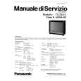
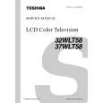
TOSHIBA 32WLT58
Diagrama del circuito


¡Twitee acerca de este producto y obtenga $1.00 de crédito en la tienda para uso!
  • Contiene diagramas del circuito
  • Descargable
  • Formato PDF
  • Idiomas: English
Precio: $4.99

Descripción del TOSHIBA 32WLT58 Diagrama del circuito

Conjunto de diagramas del circuito. Los diagramas serán proporcionados en un archivo PDF. El archivo será enviado después de que realice la compra.

The manual is available in languages: English

Not yet ready
You must purchase it first

Opiniones de los clientes
No hay comentarios de productos.

TEXT_PDF_SNIPPET
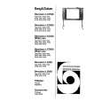
SCHEMATIC DIAGRAM
MODEL : 32WLT58/37WLT58
WARNING: BEFORE SERVICING THIS CHASSIS, READ THE "SERVICE SAFETY PRECAUTIONS" ON PAGE 3 OF THIS MANUAL. CAUTION: The international hazard symbols " " in the schematic diagram and the parts list designate components which have special characteristics important for safety and should be replaced only with types identical to those in the original circuit or specified in the parts list. The mounting position of replacements is to be identical with originals. Before replacing any of these components, read carefully the PRODUCT SAFETY NOTICE on the MANUAL for this model. Do not degrade the safety of the receiver through improper servicing.

NOTE: 1. RESISTOR Resistance is shown in ohm [K = 1.000, M = 1.000.000]. All resistors are 1/6W and 5% tolerance carbon resistor, unless otherwise noted as the following marks. 1/2R = Metal or Metal oxide of 1/2 watt 1/2S = Carbon compsistion of 1/2 watt 1RF = Fuse resistor of 1 watt 10W = Cement of 10 watt K = ±10% G = ±2% F = ±1% Unless otherwise noted in schematic, all capacitor values less than 1 are expressed in F, and the values more than 1 in pF. All capacitors are ceramic 50V, unless otherwise noted as the following marks. Electolytic capacitor
3. The parts indicated with " Mylar capacitor

2. CAPACITOR

" have special characteristics, and should be replaced with identical parts only.

4. Voltages read with DIGITAL MULTI-METER from point indicated to chassing ground, using a color bar signal with all controls at normal, line voltage at 220 volts. 5. Waveforms are taken receiving color bar signal with enough sensitivity. 6. Voltage reading shown are nominal values and may vary ±20% except H.V.

Quizás también quiera comprar

$4.99

32WLT58 TOSHIBA
Manual de Usuario

Manual del propietario completo en formato digital. El manual estará disponible para descarga como …

$4.99

32WLT58 TOSHIBA
Manual de Servicio

Manual de servicio completo en formato digital (archivo PDF). Los manuales de servicio por lo genera…
>
Parse Time: 0.214 - Number of Queries: 105 - Query Time: 0.053