|
|
|
Productos
|
|
Información
|
|
Destacado
|
|
|
 |
|
|
No hay comentarios de productos.
Circuit Descriptions and Abbreviation List
/R3118 (= 5 W). This voltage is a measure of the current and if it exceeds 1.4 V, TS7101 will be driven into conductivity and consequently connects the gate of TS7102 to earth. The FET will block. The current is: 1.4 V / 5 W = 0.28 A. The voltage across the secondary winding (8,9) will be negative, diodes D6111 and D6107 will block. Time interval t1 - t2: The sudden current interruption in the primary coil will induce a counter-e.m.f. that wants to maintain the current. The voltage on the drain of the FET will increase. The secondary voltage (8, 9) will become positive and will charge C2104 via D6111. All energy that was stored in L5101 during t0 - t1 will be transferred into the load. Due to the transformer principle, a voltage will now be induced in the primary winding (3, 5) and the cocoupled winding (1, 2). This voltage will be N* USEC (N= winding ratio). The voltage across the co-coupled coil will be negative, keeping the FET blocked. Time t2: At t2, the current through the secondary coil will be reduced to zero, as C2104 is no longer charged. As a consequence, the voltages will decay and will change polarity. The gate of the FET will be again made positive, is driven into conductivity and the cycle starts again.
EM3E
9.
GB 97
Tuner Supply The Standby supply produces 2 voltages for the Tuner: +33V (VTUN) and +5VT. � The +33V is the tuning voltage for the Tuner. � The +5VT is derived from the +8V with stabiliser 7911, and is used to supply the tuner only. SSB Supply There are several voltages going to the SSB: +8V, +5V and +3V3. � The +5V and +(always present) come directly from the Standby power supply. � The +3V3 is derived from the +5V with stabiliser 7910 (on the LSP).
9.3.4 Main Supply (diagram A1)
�
�
Some important notes on beforehand: � VBAT is not isolated from the main supply ('hot'). � VBAT is alignment free.
Feedback and stabilisation
The Standby Power Supply always oscillates at maximum power. The only limiting factor is the maximum primary current, which has been pre-set with R3108//3118. R3114, R3124, R3113 and zener diode D6122 determine UOUT. If the voltage across R3114 exceeds the threshold voltage of the diode of the optocoupler 7104 (± 1 V) or, in other words, UOUT exceeds 5.2 V, the transistor of the optocoupler will conduct. Transistor TS7100 is now driven, and a negative voltage will be transposed to the emitter of TS7101. When TS7101 conducts, the gate of the FET is at earth potential, forcing the oscillator stop. Due to the load, the secondary voltage OUT will decrease. At a certain voltage, optocoupler TS7104 will block and the oscillator will start again. Since there are no capacitors, and there is a high amplification factor in the feedback circuit, the feedback is ultra-fast. This is why the ripple on UOUT is minimal. The negative supply voltage (-13 V) used in the feedback circuit, originates from the co-coupling coil and is rectified through D6103. Stabilisation is not affected through duty-cycle control but through burst-mode of TS7100. Burst-mode is load dependent. If the power supply is less loaded, the secondary voltage will have the tendency to increase more rapidly. If the load on the power supply increases, then the oscillator stops less often, right up to the moment that the oscillator is operating continuously: maximum load. If the power supply is now loaded even more, the output voltage will decay. The maximum primary current set by R3108//3118 determines the maximum load.
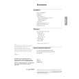
Principle The Main Power Supply, generates the 141 V (VBAT) and the +/- 16 V for the audio part. It is based on the so-called 'down converter' principle.
S
L Vin IT D + C RL VBAT
S ID L Vin D + C RL VBAT
Sclosed
Sopen
IT
δT T
ID
V
. BAT = VIN δT T
96532156_022.eps 060100
Protection If the optocoupler would fail, the secondary voltage will
increase. This would have disastrous consequences since many ICs (e.g. OTC, Flash-RAM and DRAM) are fed with this 5.2 V. In other words; very expensive repairs would be required. We already know that the negative supply is directly dependent upon the secondary 5.2 V, as a consequence of which the negative supply will increase proportionally as the secondary voltage increases. If the negative supply in the mean time reaches -15 V, D6106 will start to zener and as a consequence TS7101 will start conducting. Basically, D6106 will take over the stabilisation task of the optocoupler, however, with a considerable spread: from -13 V to -15 V is a 15 % increase, thus OUT will increase from 5.2 V to max. 6 V. � �
Figure 9-5 After closing switch 'S', the linear in time increasing current IT, will charge capacitor C. Opening switch 'S' will generate a counter-e.m.f. in coil L, trying to maintain current IT. This is possible via diode D (this diode is also called 'freewheel diode'). So after opening 'S', the magnetic energy stored in coil L will be transferred to electrostatic energy in capacitor C. The VIN will only supply current during the time that 'S' is closed while a constant current is flowing through RL. VBAT is directly proportional with VIN and the time that 'S' is closed and reverse proportional with period time 'T'. So by changing the duty cycle, it will be possible to control VBAT.
�
|
|
|
> |
|